
Modeling and Analysis of a
V6 Engine
During a mechanical design practice course, the students were tasked to propose an idea for a mechanical system that they would design, model, simulate, and analyze throughout the semester. My proposal was that of a V6 Engine.
Please click here to see final report.
I started off the design by studying the primary components of an engine, as I had very little prior experience/understanding of internal combustion engines. This led me to focus on the basic components of an engine.
Once the components had been selected and studied, the focus was shifted to studying the interaction of the components. Specifically, how the combustion of fuel would lead to the linear motion of the piston heads, causing rotational output through the crankshaft via the connecting rods.
Approximate measurements were used based on online research of the average dimensions and material of each component. These approximate dimensions were followed while designing the components in Solidworks.
The most complicated of which was the crankshaft, which uses mounting points for the connecting rods (called rod journals) offset from the center of the crankshaft itself. This offset, combined with the angular offset around the crankshaft between rod journals, 60° in this case, is what decides the firing order of the pistons.
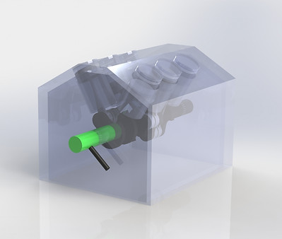
Final Engine Render
The bulk of the work on the project was spent assembling the engine and tweaking it to get it to run as smoothly as possible. Initially, testing was done by simply dragging the black handle extruded from the green side of the crankshaft to manually turn the engine over. Next, a constant angular rotation was applied to the green rod on the crankshaft.
Finally, the combustion of fuel in an actual engine was simulated by applying force to the top of the piston heads at set intervals. This timing became very difficult as Solidworks' distance trigger (applying force when the piston head is at a certain distance from the top of the engine block) could not be precise enough to simulate the compression and combustion of fuel. Thus, the applied forces were instead timed. This timing was tweaked to get as smooth of a rotation as possible.
As you can see from the video, Solidworks did not allow me to tune the force applied and timing of force quite precisely enough to stop the engine from taking off at a very high RPM. However, the motion during the rotations was very smooth and followed the correct firing order.